
Setting up the environment needed to begin with STM32
Hey guys,
So how are you guys? Hope you all are doing well.
From the last article, we told you that we will be looking into the programming side of STM32. But, we thought it would be much better for you guys, if we can give an idea about the hardware you need to do the programming with STM32 first. So today’s article will be about the hardware you needed to program a STM32, and the step by step guide to settle them with your PC.
So the topics for today are as follows.
1 - Choosing a STM32 chip/Development Board for learning purposes
2 - Methods of programming the STM32 chip/Development Board
3 - Installing STM32CubeIDE
1 - Choosing a STM32 chip/Development Board for learning purposes
As I mentioned in the previous post, the STM32F1 series and the STMF4 series are the most suitable series for a beginner. For a price of RS 700-1000 range, you can easily buy a STM32F103C8 Development Board in Sri Lanka. F4 series’s Nucleo Boards (having chips like STM32F401, STM32F411, etc) are a little bit high in cost in Sri Lanka. So because of the cost issue, we would recommend a STM32F103C8 board for testing purposes.
The chip we are using in our micromouse is STM32F405. The F4 series has a greater processing power and many other advantages (higher flash memory,SRAM, etc) than the F1 series, but it should be mentioned that we can use the STM32F103C8 board to check every sensor, actuator, etc. that we are using in our mouse . So that you don’t need to wait until you completely build your mouse, you can check every function you are planning to use in your mouse, using the STM32F103C8 board (Bluepill).
Following shows a STM32F103C8 Development Board (Bluepill) & the chip (STM32F103C8) used in it
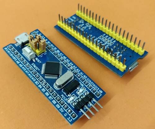
STM32F103C8 Development Board (Bluepill)
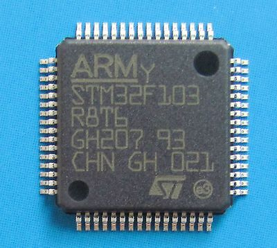
STM32F103C8 chip
This one here is a STM32 Nucleo F411RE Development Board
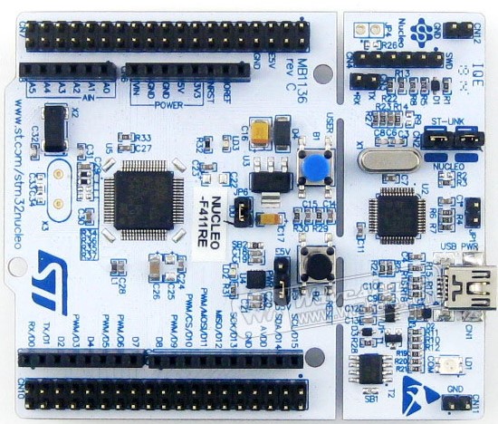
STM32 Nucleo F411RE Development Board
This is the STM32F405RGT6 chip (Chip we will be using in our mouse)
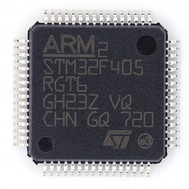
STM32F405RGT6 chip
For this STM32 guide, the requirement of a STM32 development board or a built robot using a STM32 chip is mandatory.
2 - Methods of programming the STM32 chip/Development Board
Have you guys ever heard about a STLink or a TTL?
Normally, there are two main ways of programming a STM32 chip.
1 - Using a STLink
2 - Using USB - TTL converter
STLink
Mainly there are 3 types of STLinks.
1 - Standard STLink
2 - STLink Dongle
3 - On Board STLink
This one here is a Standard STlink and is a bit more expensive than a STLink Dongle and also has more debugging functionalities than a STLink Dongle.
Standard STlink
This is a STLink Dongle and it is the most popular STLink type because of the lower price (RS 650 - 700) than the other types.
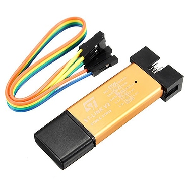
STLink Dongle
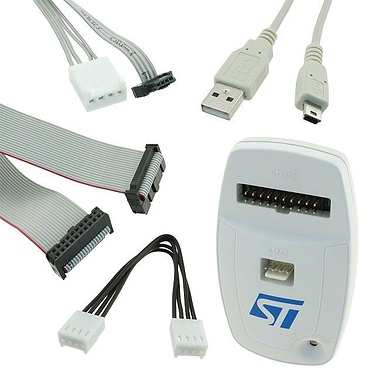
Onboard STLinks comes along with Nucleo development boards as shown in the following picture and you can also use this STLink to program any other STM32 chip. The advantage of Nucleo boards is, you can use USB - Mini cable to directly program your board.
Onboard STLinks comes with Nucleo Development Boards
There are 4 pins mainly required to program a STM32 chip using a STLink.
1 - VCC (Power pin)
2 - GND (Ground pin)
3 - SWCLK (Clock)
4 - SWDIO (Data)
Additionally there’s an optional pin called SWO. This pin is only available at Standard STLinks and does not come with STLink Dongles. The advantage of this pin is it can be used to trace data.
Wiring diagram of a STLink dongle with STM32F103C8(Bluepill) Development Board is as follows..
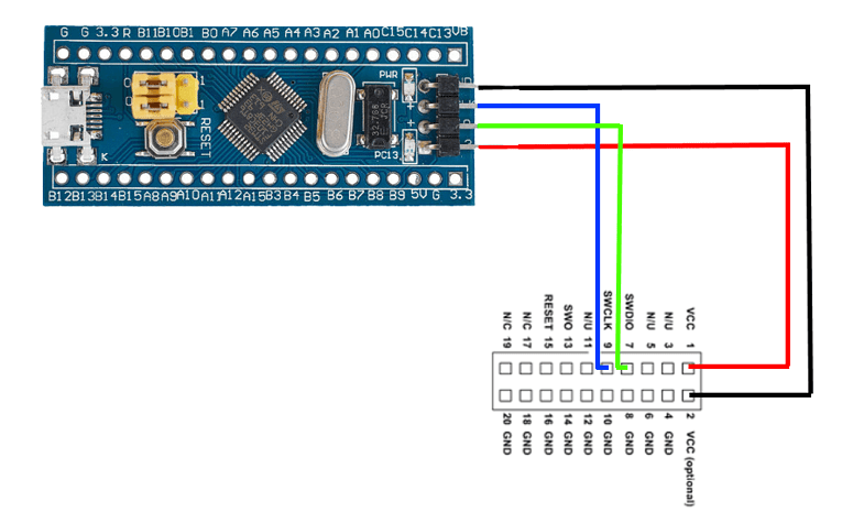
Wiring diagram of a STLink dongle with STM32F103C8(Bluepill) Development Board
In our STM32 guide, we will be using STM32CubeIDE to program our mouse and you can use any one of the three STLinks that we have mentioned above to program your STM32 chip using STM32CubeIDE.
TTL
Here is an USB - TTL converter programmer.
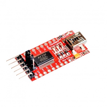
USB - TTL converter programmer
When using this, the communication happens through UART protocol. So you need to connect pins in your TTL programmer with STM32F103C8 Development Board as follows.
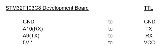
Pin connections with TTL
This picture shows the wiring.
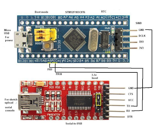
Wiring diagram with TTL
But you need to be aware of one thing when using this method. Make sure the boot 0 jumper pin on the board is set to 1 (programming mode) while uploading the boot loader. Once the boot loader is flashed this pin can be changed back to initial position (operating mode).
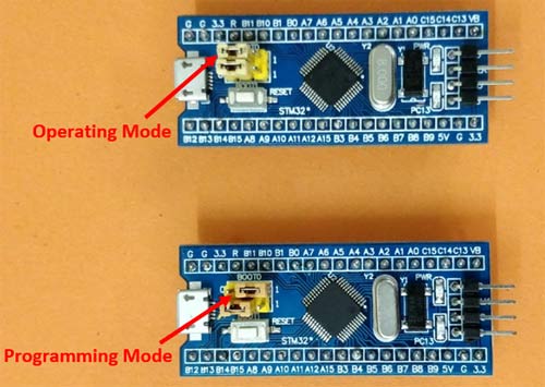
Wiring diagram with TTL
To use this method to program a STM32 chip using STM32CubeIDE, you need an additional software called STM32 Flash Loader Demonstrator.
What actually happens is, first you write your code in STM32CubeIDE and get the .bin file or .hex file and then using STM32 Flash Loader, you can upload it to the STM32 chip.
It should be noted that using this method, you cannot debug your program using CubeIDE.
You can download STM32 Flash Loader Demonstrator using this link
3 - Installing STM32CubeIDE
Now, you have a STM32 chip/Development Board and a suitable programmer ready with you. Next step is installing the editor required to edit your code. We are using STM32CudeIDE as our editor and it is required that you also have the same if you are following this guide.
You can download STM32CubeIDE using this link as we mentioned in the previous post
If you’re planning to download more products from ST, it will become easier if you have an account. Creating an account is absolutely free.
So see you guys.
Cheers!